A Coordinated Electric System Interconnection Review—the utility’s deep-dive on technical and cost impacts of your project.
Challenge: Frequent false tripping using conventional electromechanical relays
Solution: SEL-487E integration with multi-terminal differential protection and dynamic inrush restraint
Result: 90% reduction in false trips, saving over $250,000 in downtime
The three operating regions you have to design to
| Device | Output vs voltage | Response | Best suited to | Main limitations |
|---|---|---|---|---|
| Mechanically switched capacitor or reactor | Proportional to voltage squared | Seconds; discrete steps; limited switching operations per day | Steady-state reactive supply, voltage profile, loss reduction | No dynamic capability; step voltage change on switching; capability collapses when most needed |
| Static var compensator | Capacitive branches proportional to voltage squared | A few cycles; continuously controllable | Continuous control where cost matters and deep voltage support is not the driver | Square-law capability loss; harmonic filters are part of the plant and interact with the network |
| STATCOM | Approximately proportional to voltage — constant current capability | One to two cycles closed loop; converter response faster still | Voltage stability margin, weak interconnections, fast disturbance recovery, flicker and unbalance compensation | Higher capital cost; converter losses; adds a converter and its control dynamics to the network |
| Synchronous condenser | Governed by machine capability and excitation | Excitation response in the hundreds of milliseconds; inherent inertial response instantaneous | System strength and inertia, short-circuit contribution, black start support | Rotating plant with maintenance and losses; slower controlled response than a converter |
| STATCOM with energy storage | Reactive as a STATCOM, plus real power within the storage rating | As STATCOM for reactive; real power limited by storage | Where a real power deficiency is part of the problem | Cost and complexity of the storage; different failure and maintenance profile |
| Stage | Keentel scope | Outcome |
|---|---|---|
| Screening | Series-compensation proximity, radial contingency review, UIF and short-circuit ratio screening, frequency scans | Early identification of which SSO types apply |
| Detailed studies | PSCAD/EMTDC EMT studies with vendor real-code models, impedance-based and frequency-scan analysis | Clear evidence of stability margins or risk |
| Model quality | EMT model review, benchmarking against positive-sequence models, model acceptance support | Models that system operators accept |
| Mitigation | Control retuning recommendations with vendors, SSDC and bypass logic requirements, protection and monitoring specifications | Practical, coordinated solutions |
| Interconnection support | SSR and SSO study reports for ISO and utility requirements, response to reviewer comments | Fewer delays in the interconnection process |
Resilience: designing CDUs to the facility Tier objective
Liquid cooling makes heat removal more critical, not less. Cold plates hold only seconds of thermal buffer. If TCS flow stops, processors throttle or shut down very quickly. Resilience design must therefore cover:
- Pump redundancy: N+1 pumps at minimum, with automatic changeover.
- CDU redundancy: N+1 CDUs on a common TCS header, or 2N CDUs serving A and B manifolds for fault-tolerant designs.
- Power to CDUs: dual-corded CDUs fed from A and B sources, with pumps and controls on UPS power so coolant keeps flowing through a utility failure and generator start. This is the liquid-cooling equivalent of continuous cooling.
- Facility water continuity: chilled water or condenser water must also continue, through thermal storage, UPS-backed pumps or a high enough FWS temperature that the TCS can coast on stored thermal mass for the transfer period.
- Concurrent maintainability: isolation valves so any CDU, pump, filter or manifold section can be serviced without stopping the others.
- Leak management: leak detection, drip trays, automatic isolation valves and procedures for fluid spills.
Electrical engineering considerations
CDUs and liquid-cooling plants are electrical loads with their own design requirements:
- Pump motors and VFDs. Large CDUs use variable-frequency drives on their pump motors. These introduce harmonic current that must be included in the facility's harmonic study and IEEE 519 evaluation.
- Critical mechanical load on UPS. Putting CDU pumps on UPS increases UPS and battery sizing. The mechanical UPS load must be included in redundancy and ride-through calculations.
- Feeder and protection design. Dual feeds, automatic transfer, selective coordination and arc-flash labelling apply to CDU power distribution just as they do to IT power.
- Generator transient response. CDU pumps restarting together after a transfer create motor inrush on the generators. Staged restarts and soft acceleration reduce the step load.
- Load dynamics. AI training loads can swing rapidly between high and low power. Cooling controls must track those swings without temperature overshoot, and electrical systems must handle both the IT and the cooling load changes.
Commissioning a liquid-cooled data hall
- Flush and clean the TCS piping and manifolds to the specified cleanliness, using high-purity flush water.
- Fill and vent with the specified coolant, verifying glycol concentration and chemistry.
- Pressure test for leaks at design and test pressures, including quick-disconnect fittings.
- Verify sensors and controls: flow meters, temperature sensors, pressure transmitters, leak detection and BMS points.
- Load test with heat load banks connected through the cold-plate interfaces or rack manifolds, across the operating range.
- Prove the heat balance on both loops at several load steps, and the approach temperature against the design.
- Test failure scenarios: pump failure, CDU failure, power transfer to generator, valve failure and loss of facility water, confirming temperatures stay within the IT vendor's limits.
How Keentel Engineering helps
Keentel Engineering supports data center owners, developers and EPCs with the electrical engineering that liquid-cooled facilities depend on, and coordinates with the mechanical engineer of record and cooling vendors on the integrated design.
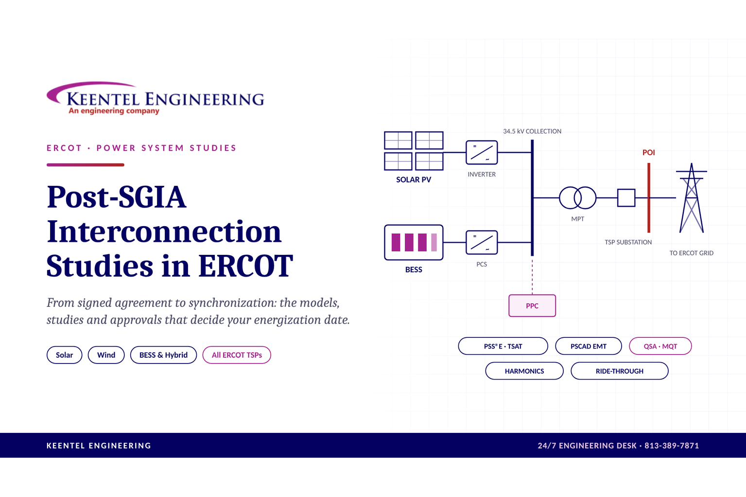
Post-SGIA Interconnection Studies in ERCOT: From Agreement to Synchronization
October 28, 2026 | Blog
Why the work after the SGIA decides your energization date
Signing the Standard Generation Interconnection Agreement (SGIA) does not mean you are cleared to energize. In ERCOT, a solar, wind or battery project still has to replace its preliminary models with as-built ones, pass ERCOT's model checks, clear a Quarterly Stability Assessment, and satisfy its Transmission Service Provider (TSP) before the first breaker closes.
This stretch is where schedules slip. The studies have to be built on final vendor data, they are reviewed by both ERCOT and the TSP, and each round of comments can cost a quarter.
This article covers what the post-SGIA phase involves, how it differs between ERCOT's TSPs, the studies you will need, and how Keentel Engineering supports EPCs, developers and owners through it. It closes with three anonymized case studies and a detailed FAQ.
Where post-SGIA sits in ERCOT's interconnection process
In ERCOT, "post-SGIA" covers everything from the signed interconnection agreement to Part 3 commercial operation. ERCOT's own process material puts a large project (10 MW or more) at 18 to 30 months from request to the Quarterly Stability Assessment (QSA), before construction and supply delays. The post-SGIA steps decide whether the back end of that schedule holds.
The sequence for a typical solar, wind or BESS project:
- Generation Interconnection Request (GINR) studies. Screening Study, then the Full Interconnection Study (FIS), which includes the steady-state, short-circuit, stability, reactive and, where needed, sub-synchronous resonance (SSR) studies.
- SGIA executed with the TSP. The execution date matters: projects with an SGIA on or after 1 August 2024 must meet ERCOT's preferred voltage ride-through requirements and IEEE 2800-2022 under NOGRR 245.
- As-built model package. Final PSS®E, TSAT and PSCAD models built from the purchased equipment, with Model Quality Test (MQT) reports and unit model validation, submitted through ERCOT's RIOO system.
- Quarterly Stability Assessment. ERCOT studies the project in a quarterly cycle. Models, PSCAD files and MQT reports must be in ahead of that cycle's deadline, or the project waits for the next quarter.
- Resource registration and commissioning plan. Full registration data, telemetry and metering set-up, and a commissioning plan filed in RIOO.
- Part 1: energization. The TSP confirms POI protection settings against the approved coordination study and back-feeds the plant.
- Part 2: initial synchronization. Requires the ride-through capability package to be submitted first. Output above 20 MVA is released in hold-point steps.
- Part 3: commercial operation. Field tests cover reactive capability, voltage regulation, primary frequency response and curtailment. The final model and verification package follows.
The studies and models in steps 3 to 8 are reviewed by two parties with different interests: ERCOT, which cares about system stability and model fidelity, and the TSP, which cares about its protection, power quality and switching procedures. Most delays come from one of the two sending comments back late in the cycle.
The Transmission Service Providers across ERCOT
ERCOT runs the grid and the market, but your plant connects to a Transmission Service Provider (TSP). The TSP signs the SGIA, builds or owns the interconnection facilities, and has its own technical requirements on protection, telemetry, power quality and switching. Keentel works with projects across all of ERCOT's TSPs, from the large investor-owned utilities to municipal systems and electric cooperatives.
The principal TSPs a renewable or storage project is likely to connect to:
| Transmission Service Provider | Type | Where it operates in ERCOT |
|---|---|---|
| Oncor Electric Delivery | Investor-owned | North, Central and West Texas, including Dallas–Fort Worth and the Permian Basin |
| CenterPoint Energy Houston Electric | Investor-owned | Greater Houston and the upper Gulf Coast |
| AEP Texas | Investor-owned | South Texas, the Coastal Bend, the Rio Grande Valley and west-central Texas |
| Electric Transmission Texas (ETT) | Transmission-only joint venture | Across ERCOT, including CREZ and South Texas facilities |
| Texas-New Mexico Power (TNMP) | Investor-owned | Gulf Coast, north-central Texas and the Permian Basin |
| LCRA Transmission Services Corporation | Public, non-profit | Central Texas and the Hill Country |
| CPS Energy | Municipal | San Antonio and Bexar County area |
| Austin Energy | Municipal | Austin and Travis County area |
| Brazos Electric Power Cooperative | Generation and transmission cooperative | North-central Texas and the Brazos River corridor |
| South Texas Electric Cooperative (STEC) | Generation and transmission cooperative | South Texas |
| Lone Star Transmission | Transmission-only (CREZ) | West and north-central Texas |
| Wind Energy Transmission Texas (WETT) | Transmission-only (CREZ) | Panhandle and West Texas |
| Cross Texas Transmission | Transmission-only (CREZ) | Panhandle and West Texas |
| Rayburn Country Electric Cooperative | Generation and transmission cooperative | Northeast Texas |
| Lubbock Power & Light | Municipal | Lubbock area |
| Texas Municipal Power Agency, Bryan Texas Utilities, College Station, Garland Power & Light, Denton Municipal Electric, GEUS, Brownsville PUB, New Braunfels Utilities | Municipal | Their local service areas |
The list is not exhaustive. Your TSP is named in your GINR and SGIA.
What changes from one TSP to the next
ERCOT's modeling and commissioning rules are the same for every project. What varies is the TSP layer on top:
- Facility interconnection requirements. Each TSP publishes its own requirements under NERC FAC-001, covering protection, metering, telemetry and design standards.
- Protection philosophy. Line differential versus distance schemes, direct transfer trip, breaker failure, relay platforms and the settings coordination process at the POI.
- Telemetry and communications. RTU type, ICCP points, communication paths and the data the TSP needs before back-feed.
- Power quality limits. How the TSP applies IEEE 519 harmonic limits and flicker criteria at the POI, and what background harmonic data it will share.
- Energization procedures. Switching orders, inrush limits, hold points and what must be studied before the first breaker close.
- Review cadence. How fast comments come back and which group reviews what.
On a project, we start by mapping the TSP's specific requirements against ERCOT's, so one set of models and studies satisfies both reviewers.
The post-SGIA study set, in depth
Every post-SGIA package answers one question for ERCOT and the TSP: does the plant as built behave the way the models say it will? The table below shows each piece of work, who reviews it and where it falls in the process.
| Study or deliverable | What it answers | Main reviewer | When it is needed |
|---|---|---|---|
| As-built PSS®E and TSAT dynamic models | Does the positive-sequence model match the purchased inverters, plant controller and transformers? | ERCOT | Before QSA entry |
| PSCAD EMT model and studies | Does the plant stay stable on a weak grid and near other inverter-based resources? | ERCOT | Before QSA entry |
| Model Quality Tests and unit model validation | Do the PSS®E, TSAT and PSCAD models give the same response, and match the hardware? | ERCOT | Before QSA, again before Part 3 |
| Reactive capability study | Can the plant supply 0.95 leading and lagging power factor at the POI across its output range? | ERCOT and TSP | Before QSA; field-tested at Part 3 |
| Voltage and frequency ride-through | Will the plant stay online through grid disturbances, per NOGRR 245 and IEEE 2800-2022? | ERCOT | Package filed before Part 2 |
| Harmonics and power quality | Does the plant meet IEEE 519 and the TSP's flicker limits at the POI? | TSP | Before energization |
| Energization studies | Will energizing the main transformer cause voltage dips, relay misoperation or overvoltages? | TSP | Before Part 1 |
| Short circuit and protection coordination | Are the plant's and the TSP's relays coordinated at the POI? | TSP | Before Part 1 |
| SSR screening, where required | Is there a sub-synchronous resonance risk from nearby series compensation? | ERCOT and TSP | During GINR; refreshed if equipment changes |
| Model verification report | Do the final models match field settings and commissioning data? | ERCOT | Within 30 days of Part 3; again at 12–24 months |
1. As-built dynamic models (PSS®E and TSAT)
The models used in the interconnection studies are usually built on early or generic data. Post-SGIA, they must be rebuilt around the equipment actually purchased: the inverter make, model and firmware, the power plant controller (PPC) settings, the main power transformer impedance and taps, and the collection system. ERCOT requires PSS®E power flow and dynamic files, plus TSAT versions, with ERCOT now moving its models to PSS®E version 36. A model that does not match field equipment is rejected, however well it has been tested.
2. PSCAD electromagnetic transient (EMT) models and studies
Positive-sequence tools cannot show fast control interactions. ERCOT requires a PSCAD model for inverter-based resources, built from the manufacturer's real control code and submitted on ERCOT's PSCAD template. Where the POI is weak (low short-circuit ratio) or close to other inverter-based plants, PSCAD studies show whether controls interact, oscillate or lose synchronism. Getting a usable, ERCOT-compliant PSCAD model from the inverter supplier is one of the most common schedule risks.
3. Model Quality Tests (MQT) and unit model validation
The MQT runs the same set of tests in PSS®E, TSAT and PSCAD and overlays the results. The tests include flat start, voltage and frequency steps, high and low voltage ride-through, phase angle jumps and weak-grid cases. The three models must agree with each other, and with hardware or factory test data. Hybrid plants that share a transformer or plant controller need a combined MQT.
4. Reactive power capability
ERCOT requires intermittent renewable and storage resources to provide reactive power across a 0.95 leading to 0.95 lagging power factor range at the POI at full output. The study accounts for collection-system and transformer losses and charging, and decides whether capacitor banks, reactors or extra inverter capacity are needed. The same capability is then demonstrated in the Part 3 field tests.
5. Voltage and frequency ride-through
Under NOGRR 245, projects with an SGIA on or after 1 August 2024 must meet ERCOT's preferred voltage ride-through requirements and IEEE 2800-2022. Older projects must meet the legacy requirements and get as close to IEEE 2800 as reasonably possible. Before Part 2, ERCOT needs a ride-through capability package: capability curves at the Resource level, inverter and protection limits, and evidence that rate-of-change-of-frequency and phase-angle-jump settings will not trip the plant inside the no-trip zone. NERC PRC-024 and PRC-029 add their own protection-setting and ride-through obligations.
6. Harmonics, flicker and power quality
The TSP will expect the plant to meet IEEE 519 harmonic limits at the POI. The study models the frequency response of the collection cables, main power transformer, inverters and any capacitor banks, looks for resonances, and checks distortion against the limits. Flicker and voltage-step studies cover fast output changes from passing clouds and capacitor or reactor switching. If filters are needed, it is far cheaper to find out before equipment is fixed.
7. Energization and switching studies
Before the first breaker close, the TSP needs to know what will happen when the main power transformer is energized. Inrush studies estimate the voltage dip on the transmission system and check that the inrush current will not trip protection. Transient overvoltage and ferroresonance screening covers breaker operations and the open-ended collection system. The results feed the energization plan and switching order.
8. Short circuit, protection and coordination at the POI
The plant's protection must coordinate with the TSP's relays at the POI and on the line. That means an updated short-circuit model with the as-built inverter fault contribution, coordination studies, and relay settings that the TSP reviews and approves. The TSP checks these settings before it authorizes Part 1 back-feed.
9. QSA and commissioning support
The QSA runs on a quarterly cycle, and the models, PSCAD files and MQT reports must be submitted ahead of each cycle's prerequisite deadline. Missing a deadline usually means waiting a full quarter. After the QSA, the work moves to registration data, the commissioning plan, the Part 1 to 3 checklists, and the field-test reports for reactive capability, voltage regulation, primary frequency response and curtailment.
10. Post-commissioning model verification
The obligation does not end at commercial operation. ERCOT requires a final model and verification package within 30 days of Part 3 approval, an updated verification report 12 to 24 months later, and a new package within 30 days of any change to settings that affect dynamic response.
What Keentel Engineering is doing for post-SGIA projects
Keentel supports EPCs, developers and owners through the post-SGIA phase on solar, wind, BESS and hybrid projects across ERCOT, with any TSP. Our aim is one consistent set of models and studies that clears ERCOT and the TSP on the first or second pass, on the QSA cycle you are targeting.
How we run a post-SGIA engagement
- Gap review in the first two weeks. We review your SGIA, the GINR study reports, the current models and the TSP's interconnection requirements. You get a list of what is missing, who owns it, and which QSA cycle is realistic.
- Vendor data lock-down. We issue a data request to the inverter, PPC and transformer suppliers and follow it up until we have final data and an ERCOT-compliant PSCAD model.
- Model build and MQT. We build or update the PSS®E, TSAT and PSCAD models and run the Model Quality Tests, with a short report ready for ERCOT.
- TSP-facing studies. We run the reactive capability, harmonics, energization, short-circuit and protection coordination studies to the TSP's own criteria.
- Submittals and comment resolution. We prepare the RIOO submittals and respond to ERCOT and TSP comments quickly, so the project holds its QSA slot.
- Commissioning and verification. We support the commissioning plan, the Part 1 to 3 checklists and field-test reviews, then deliver the post-commissioning model verification report.
What you receive
- As-built PSS®E (v35 and v36 where required), TSAT and PSCAD model packages on ERCOT's templates
- Model Quality Test and unit model validation reports
- Reactive capability study, with sizing of any capacitor banks or reactors
- Ride-through capability package for Part 2, including NOGRR 245 and IEEE 2800-2022 evidence
- Harmonics, flicker and power quality study against IEEE 519 and the TSP's limits
- Energization study and input to the switching plan
- Short-circuit, protection coordination and relay settings review at the POI
- A comment-response log that tracks every ERCOT and TSP question to close-out
- Post-commissioning model verification report
Why EPCs bring us in
- One team, both reviewers. We build the models and the TSP-facing studies together, so they don't contradict each other.
- Scale of experience. Keentel's power system studies cover 4 kV to 765 kV, with interconnection, protection, NERC compliance and owner's engineer services under the same roof.
- Fits around your engineer of record. We take the specialist studies, and your EOR keeps the design. We agree the boundary at kick-off.
- Built for schedule. Every engagement is planned backwards from your QSA deadline and target synchronization date.
Three anonymized case studies
Client names, project names, locations and exact figures are withheld. The details are generalized to protect confidentiality.
Case study 1: Utility-scale solar, Gulf Coast, held its QSA window after an inverter change
Situation. An EPC took over a utility-scale solar project after the SGIA was signed. During procurement, the owner switched to a different inverter model from the one used in the interconnection studies. The existing PSS®E and PSCAD models no longer matched the plant, and the next QSA prerequisite deadline was about ten weeks away.
What we did. We ran a gap review in the first week and showed which studies had to be redone. We worked directly with the inverter supplier to get an ERCOT-compliant PSCAD model, rebuilt the PSS®E and TSAT models around the new equipment, and reran the MQT. The reactive capability study showed the plant was short of the 0.95 lagging requirement at full output, so we sized a capacitor bank before the substation design was frozen.
Outcome. The model package went in before the deadline and the project stayed in its planned QSA cycle. The capacitor bank was added during design, not as a field change.
Case study 2: Solar plus BESS hybrid, Central Texas, harmonic resonance found before energization
Situation. A developer's solar and storage hybrid shared one main power transformer. The TSP asked for a harmonics study before it would approve energization, and gave background harmonic data for the POI substation.
What we did. We built a frequency-domain model of the collection system, transformer, inverters and the plant's capacitor bank. The scan showed a parallel resonance close to a characteristic harmonic, which could push distortion at the POI above IEEE 519 limits when the capacitor bank was in service. We tested options and recommended changing the capacitor bank into a tuned filter, then rechecked the reactive capability with the change. We also produced the combined MQT ERCOT requires for hybrids sharing a transformer and plant controller.
Outcome. The TSP accepted the study and the filter design. The issue was fixed on paper before equipment was ordered, rather than after a power quality complaint.
Case study 3: Wind repower in West Texas, weak-grid PSCAD study and ride-through package
Situation. An owner was repowering a wind plant at a remote West Texas POI with a low short-circuit ratio and several other inverter-based plants nearby. The amended SGIA brought the project under ERCOT's preferred ride-through requirements and IEEE 2800-2022.
What we did. We ran PSCAD studies of the plant and its neighbours under weak-grid and fault conditions. These showed a control-interaction oscillation under one outage, which was resolved by retuning plant controller gains with the turbine supplier. We then assembled the ride-through capability package for Part 2, including Resource-level capability curves, protection limits, and evidence that frequency-change and phase-jump settings would not trip the plant inside the no-trip zone.
Outcome. ERCOT accepted the ride-through package, and the tuned settings were carried into the final model and post-commissioning verification report.
Frequently asked questions
It is the phase after the Standard Generation Interconnection Agreement is signed with the TSP and before Part 3 commercial operation. It covers the as-built models, the Quarterly Stability Assessment, TSP-required studies, registration and the three commissioning parts.
The GINR studies are done, but they were based on preliminary data. Once equipment is purchased, ERCOT and the TSP need models and studies that match the real plant. Any change in inverter, transformer, collection system or plant controller can mean redoing studies.
The QSA is ERCOT's quarterly stability study of projects approaching synchronization. A project has to clear it before it can be approved to synchronize. Models, PSCAD files and MQT reports must be submitted before each cycle's prerequisite deadline. A late or incomplete package usually moves the project to the next quarter.
An MQT is a standard set of simulations run in PSS®E, TSAT and PSCAD, with the results overlaid. It proves the models are well-behaved and agree with each other and with the hardware. ERCOT requires MQT reports before the QSA and again before Part 3.
Yes. ERCOT requires a PSCAD model for inverter-based resources whatever the grid strength, on ERCOT's PSCAD template. Weak-grid locations, typically a short-circuit ratio of 2 or below, also need PSCAD studies using the manufacturer's real control code.
It depends on your SGIA date. Under NOGRR 245, projects with an SGIA on or after 1 August 2024 must meet ERCOT's preferred voltage ride-through requirements and IEEE 2800-2022. Earlier projects must meet the legacy requirements and match IEEE 2800 as closely as reasonably possible. An amended SGIA can change which rules apply, so check the agreement language.
Renewable and storage resources in ERCOT must provide reactive power across 0.95 leading to 0.95 lagging power factor at the POI at full output. The study shows whether the inverters can do it alone or need capacitor banks or reactors. The capability is field-tested at Part 3.
Typically: approved protection settings coordinated with its relays, a harmonics and power quality study, an energization study covering transformer inrush and overvoltages, working telemetry and metering, and a switching plan. Each TSP publishes its own requirements, so the list varies.
They are ERCOT's commissioning checklists. Part 1 is energization of the plant's equipment from the grid. Part 2 is initial synchronization, with output above 20 MVA released in steps. Part 3 is full commissioning, after field tests of reactive capability, voltage regulation, frequency response and curtailment.
It depends on vendor data and the QSA calendar more than on the studies themselves. With final equipment data in hand, a model package and the main studies usually take a few months. Waiting for an ERCOT-compliant PSCAD model from the inverter supplier is often the longest single item, so start that request early.
Yes. A co-located BESS adds charging and discharging modes, state-of-charge limits and its own reactive capability. Hybrids sharing a transformer or plant controller need a combined MQT. New storage capacity may also fall under ERCOT's advanced grid support requirements, which affects the models required.
ERCOT requires final models and a verification report within 30 days of Part 3 approval, an updated report 12 to 24 months later, and a new package within 30 days of any change to settings that affect dynamic response. NERC standards such as PRC-024, PRC-029 and the model validation standards also continue to apply.
Yes. Many EPCs keep their EOR for design and bring us in for the specialist modeling and studies. We agree a clear scope boundary at kick-off so nothing falls between the two firms.
Yes. We support projects connecting to any ERCOT TSP, including investor-owned utilities, transmission-only companies, municipal utilities and electric cooperatives.
References and further reading
Links were current at publication.
ERCOT process and commissioning
- ERCOT Interconnection Process: Generation Entity Winter Weather Preparedness, ERCOT, October 2024
Ride-through requirements
- NOGRR 245 Overview, RIWG, ERCOT, October 2024
- NOGRR 245 key documents, ERCOT
- IBRWG: PRC-029 and NOGRR 245, ERCOT, February 2025
Modeling and Model Quality Tests
- MQT and VRT, RIWG, ERCOT, June 2022
- ERCOT RIWG April 2026: QSA deadlines, ride-through compliance and AGS-ESR updates, Zero Emission Grid
- ERCOT Dynamic Model Submission Requirements, Keentel Engineering, May 2026
- ERCOT New Generator Commissioning Checklist 2026: Parts 1–3, Keentel Engineering
Talk to Keentel about your post-SGIA scope
Tell us your project size, your TSP, whether a battery is planned and your target synchronization date. We'll come back with a focused scope of work.
24/7 Keentel Engineering Desk: 813-389-7871
Email: contact@keentelengineering.com
Web: keentelengineering.com

About the Author:
Sandip "Sonny" R. Patel, P.E.
IEEE Senior Member · Founder & CEO, Keentel Engineering
In 1995, Sonny Patel earned his Electrical Engineering degree from the University of Illinois. But degrees don't build legacies — action does.
For three decades, he has worked the power industry from every side of the table: 16 years as a utility engineer at Exelon/Commonwealth Edison; generation leadership across hydroelectric, industrial steam turbine, and a 9 GW renewable fleet; NERC Regional Entity Senior Compliance Engineer and Audit Team Lead, auditing some of the nation's largest utilities; and testing and commissioning lead on equipment up to 765 kV — the very top of the North American grid.Utility. Generator. Regulator. Consultant. Few engineers have seen all four seats. Fewer still have sat in them.
His experience spans nuclear, hydro, conventional generation, renewables, oil and gas, mining — and today's data centers, where he is authoring a three-book series on data center design. He is a Licensed Professional Engineer in six states and a Licensed Electrical Contractor in Florida (Unlimited EC) — he doesn't just design the work; he's qualified to stand behind its execution.Today, as Founder and CEO of Keentel Engineering, Sonny leads a nationwide team of engineers delivering substation design, power system studies, NERC compliance, and commissioning — done right, coast to coast.Three decades. Every side of the table. One standard: accountable engineering.
Services

Let's Discuss Your Project
Let's book a call to discuss your electrical engineering project that we can help you with.
About the Author:
Sandip "Sonny" R. Patel, P.E.
IEEE Senior Member · Founder & CEO, Keentel Engineering
In 1995, Sonny Patel earned his Electrical Engineering degree from the University of Illinois. But degrees don't build legacies — action does.
For three decades, he has worked the power industry from every side of the table: 16 years as a utility engineer at Exelon/Commonwealth Edison; generation leadership across hydroelectric, industrial steam turbine, and a 9 GW renewable fleet; NERC Regional Entity Senior Compliance Engineer and Audit Team Lead, auditing some of the nation's largest utilities; and testing and commissioning lead on equipment up to 765 kV — the very top of the North American grid.
Utility. Generator. Regulator. Consultant. Few engineers have seen all four seats. Fewer still have sat in them.
His experience spans nuclear, hydro, conventional generation, renewables, oil and gas, mining — and today's data centers, where he is authoring a three-book series on data center design. He is a Licensed Professional Engineer in six states and a Licensed Electrical Contractor in Florida (Unlimited EC) — he doesn't just design the work; he's qualified to stand behind its execution.
Today, as Founder and CEO of Keentel Engineering, Sonny leads a nationwide team of engineers delivering substation design, power system studies, NERC compliance, and commissioning — done right, coast to coast.Three decades. Every side of the table. One standard: accountable engineering.
Leave a Comment
Thank you for contacting us.
We will get back to you as soon as possible.
We will get back to you as soon as possible.
Oops, there was an error sending your message.
Please try again later.
Please try again later.
Related Posts
By SANDIP R PATEL
•
October 30, 2026
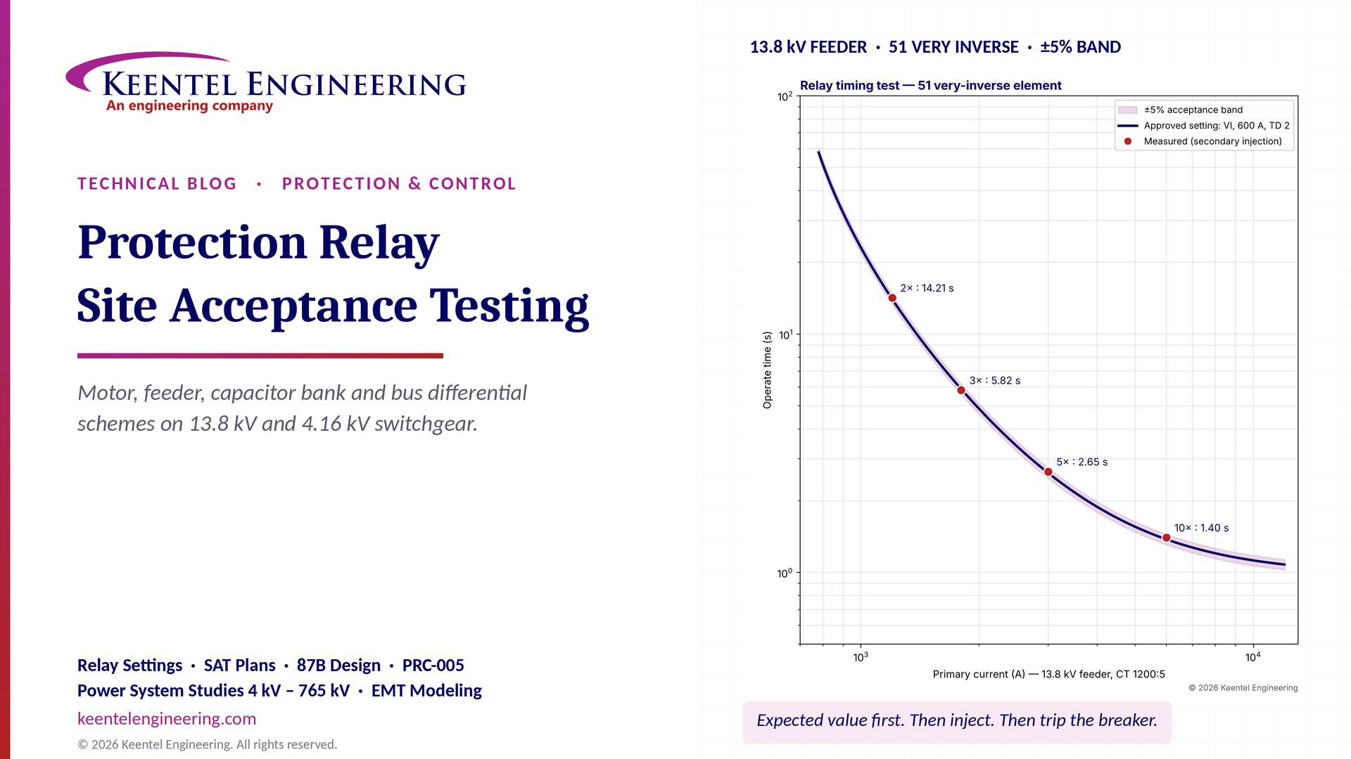
Protection relay site acceptance testing (SAT) guide covering CT/VT checks, secondary injection, motor relays, 87B bus differential and IEEE/NETA standards.

By SANDIP R PATEL
•
October 30, 2026
Understand SPP HILL requirements, HDPS interconnection studies, voltage and frequency ride-through, EMT modeling, weak-grid screening, and compliance.

By SANDIP R PATEL
•
October 28, 2026
Explore what's inside a data center rack, from servers and switches to PDU sizing, UPS, A/B redundancy, cooling and power design for high-density AI racks.
By SANDIP R PATEL
•
October 27, 2026
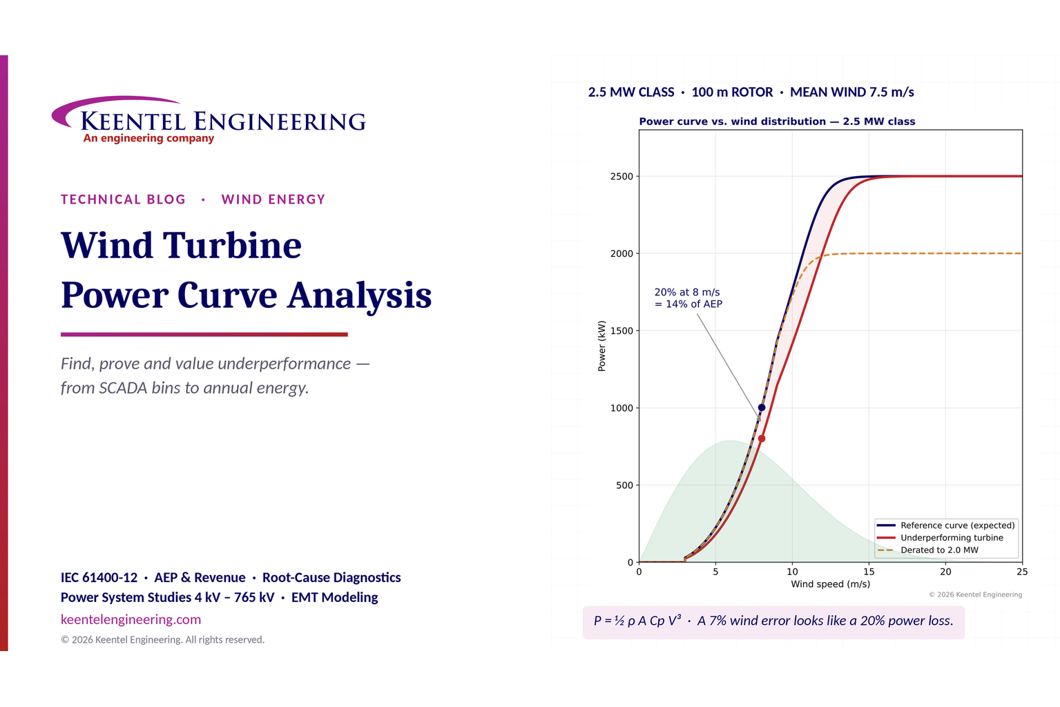
Learn wind turbine power curve analysis using SCADA data, IEC 61400-12, AEP calculations and diagnostics to identify underperformance and energy losses.
By SANDIP R PATEL
•
October 27, 2026
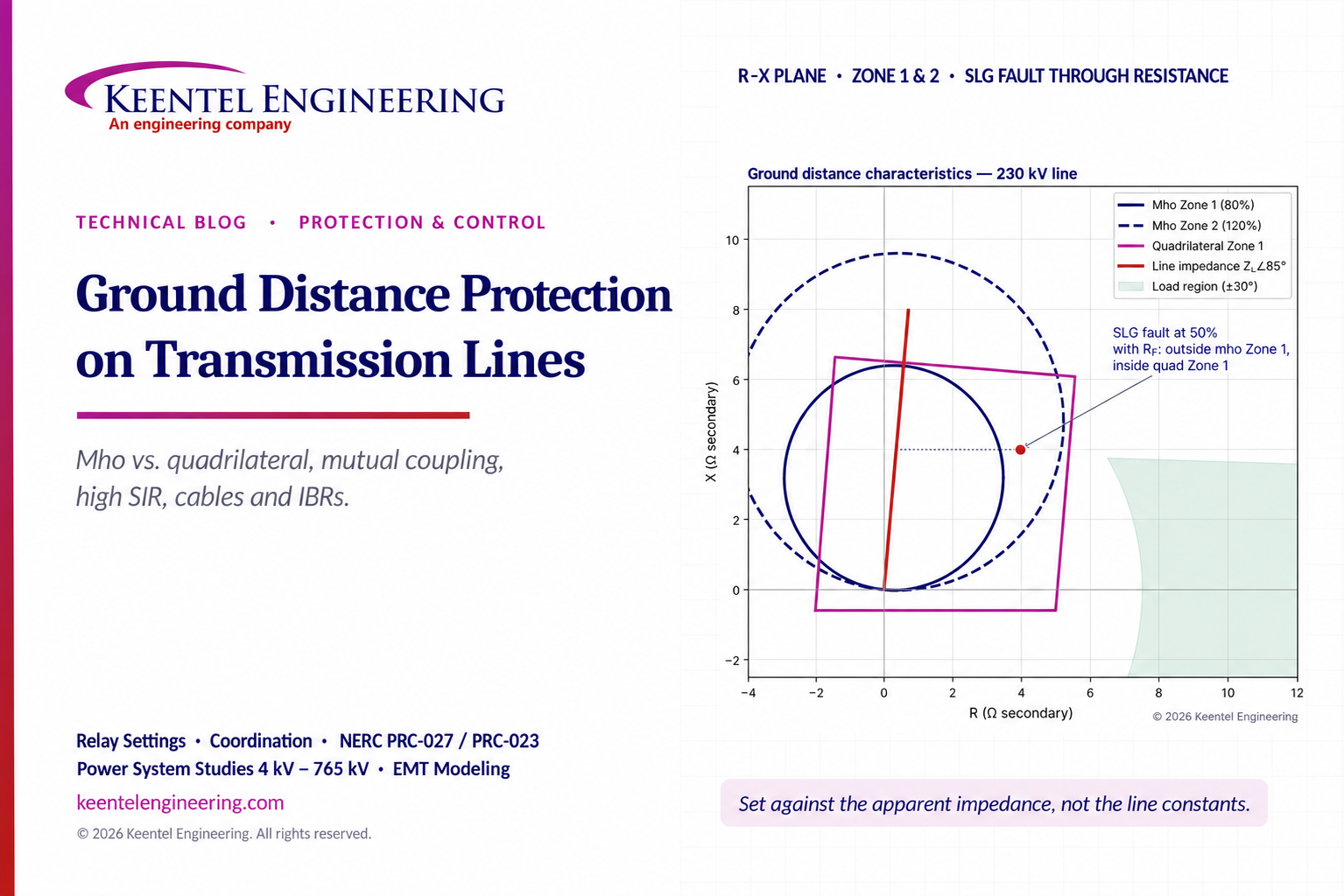
Ground distance protection guide comparing mho vs quadrilateral relays, mutual coupling, high SIR, CVT transients, IBRs and transmission line settings.
By SANDIP R PATEL
•
October 27, 2026
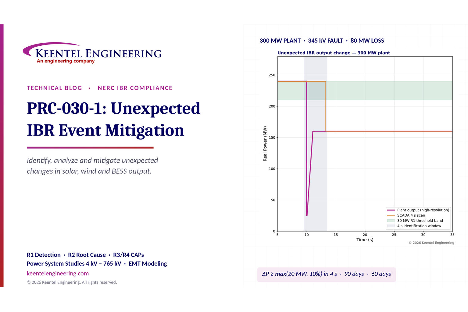
PRC-030-1 compliance guide for solar, wind and BESS owners. Learn R1-R4 requirements, 4-second event detection, root-cause analysis and CAP deadlines.
By SANDIP R PATEL
•
October 27, 2026
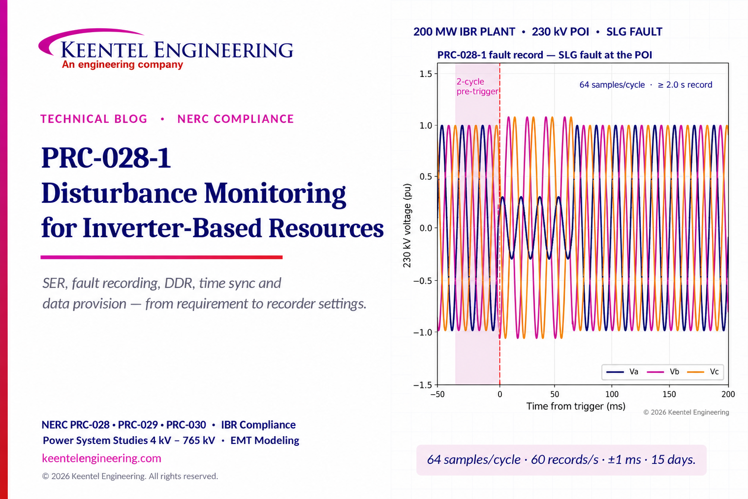
Explore NERC PRC-028-1 requirements for IBR disturbance monitoring, fault recording, SER, DDR, time synchronization, compliance deadlines and audit readiness.

By SANDIP R PATEL
•
October 26, 2026
Explore cyber-physical resilience for the Energy Internet, including DER attacks, false data injection, BESS readiness, AI detection, and NERC CIP compliance.
By SANDIP R PATEL
•
October 26, 2026
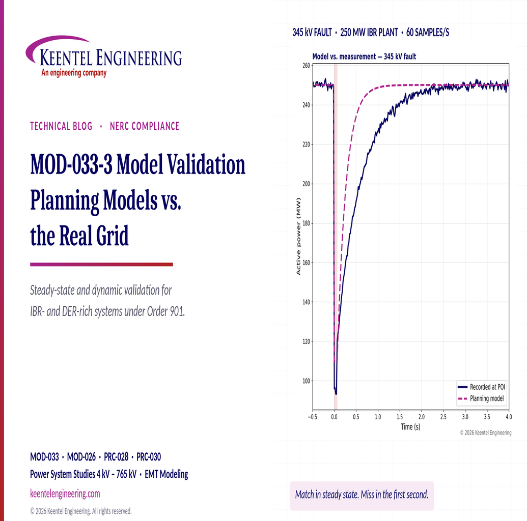
Understand MOD-033-3 requirements, IBR and DER model validation, steady-state comparisons, dynamic studies and NERC compliance.